A programmable logic controller (PLC) controls the manufacturing processes for integrated production lines and equipment. PLCs were designed to replace the need for a large bank of relays or timers in facilities with numerous inputs and outputs. Due to their durability and ability to automate multiple processes, PLCs have become a staple in modern manufacturing. In this guide, we will review the basic architecture of programmable logic controllers.
Hardware
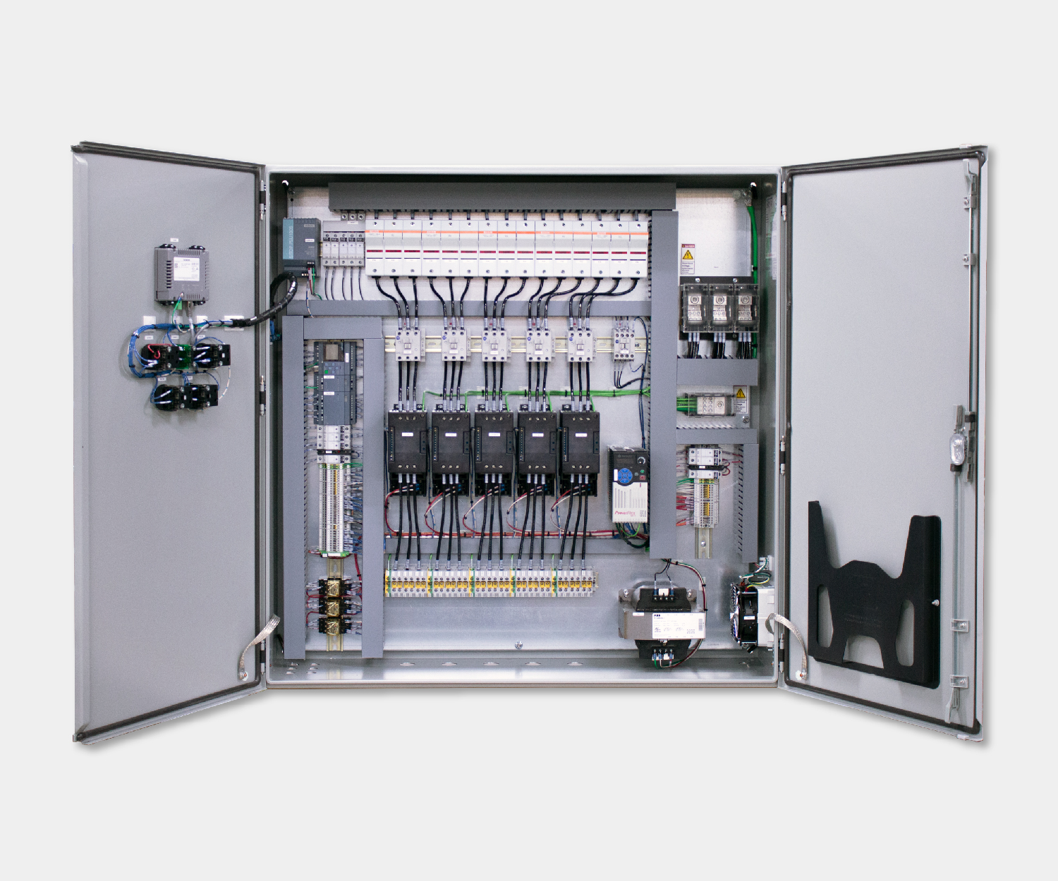
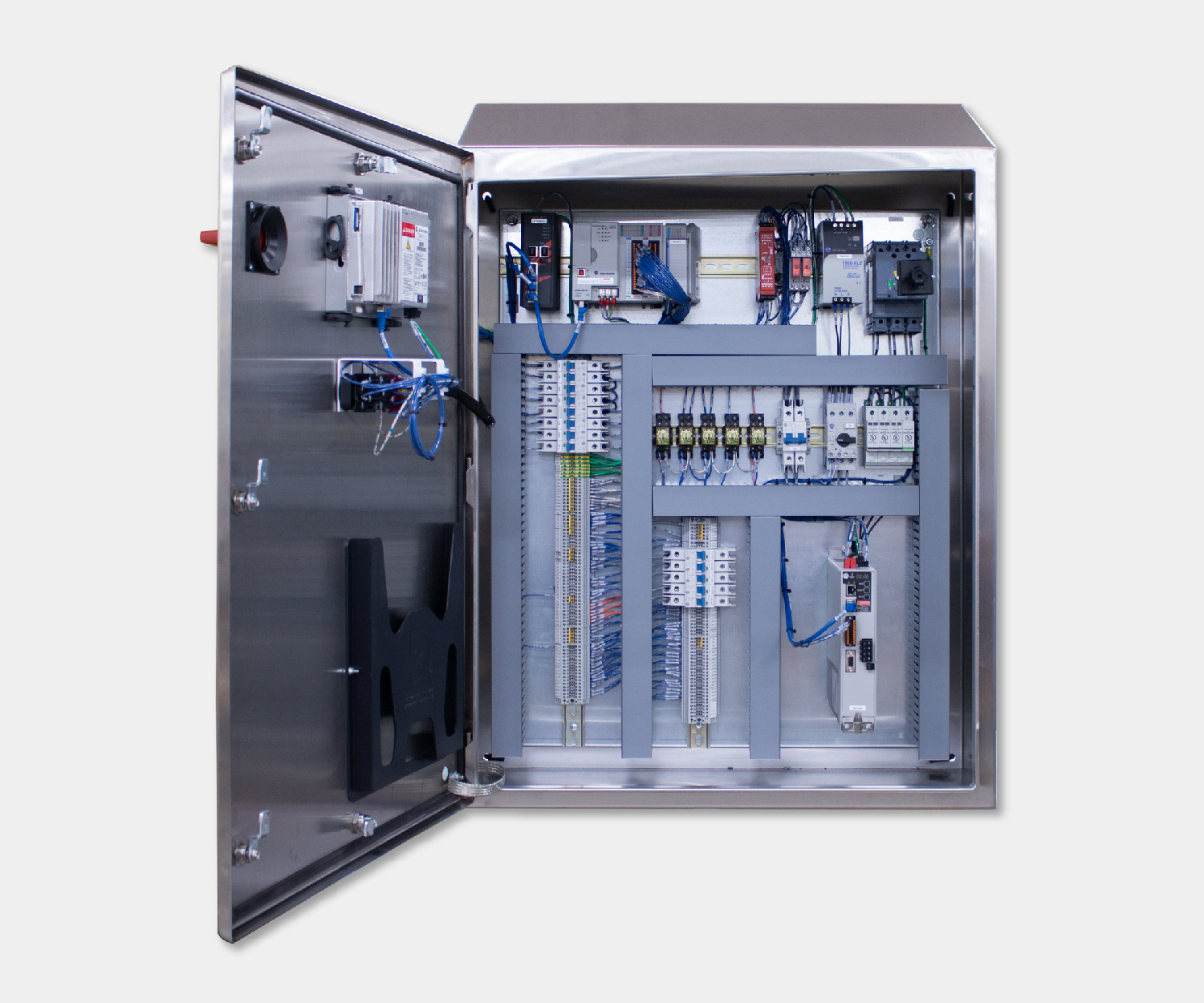
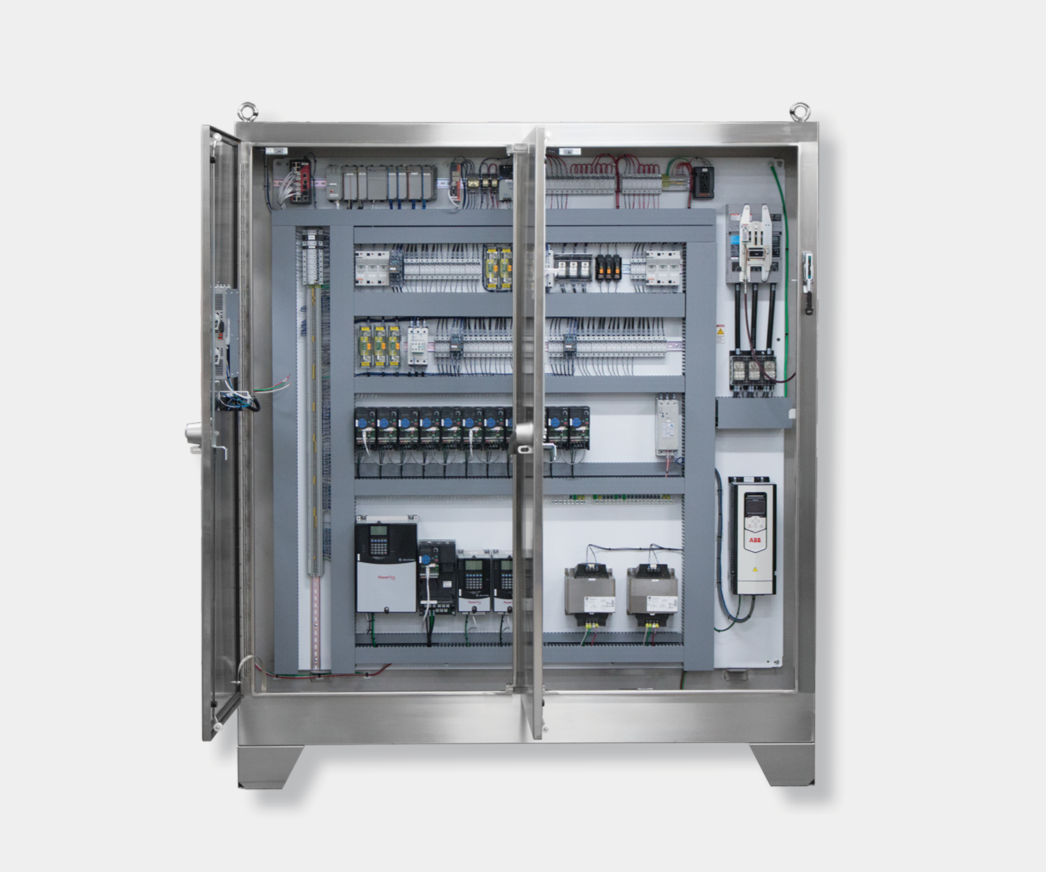
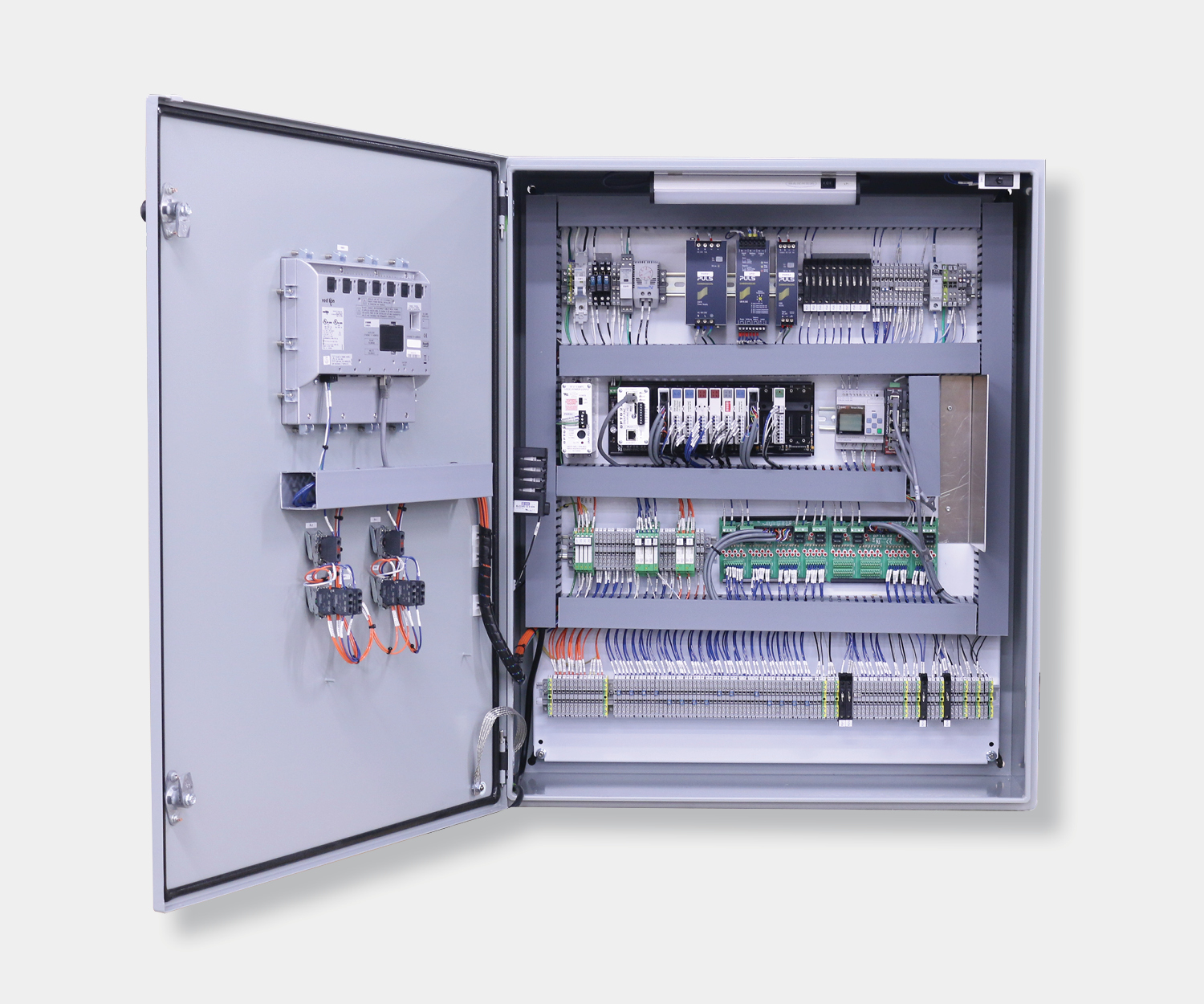
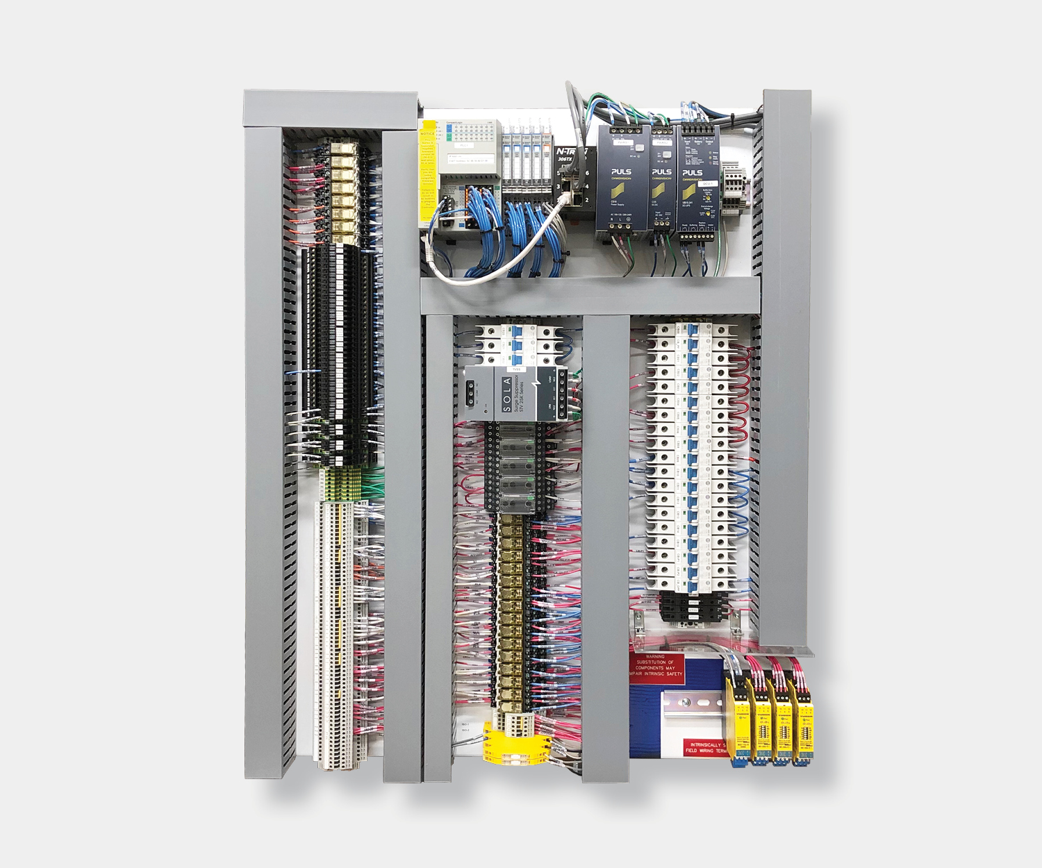
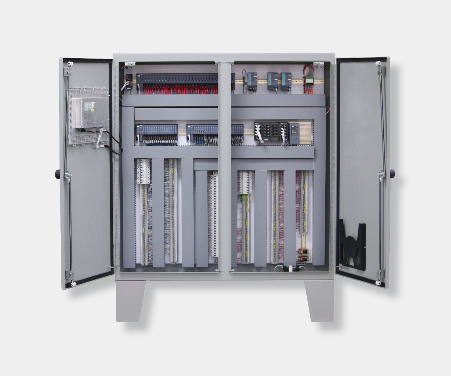
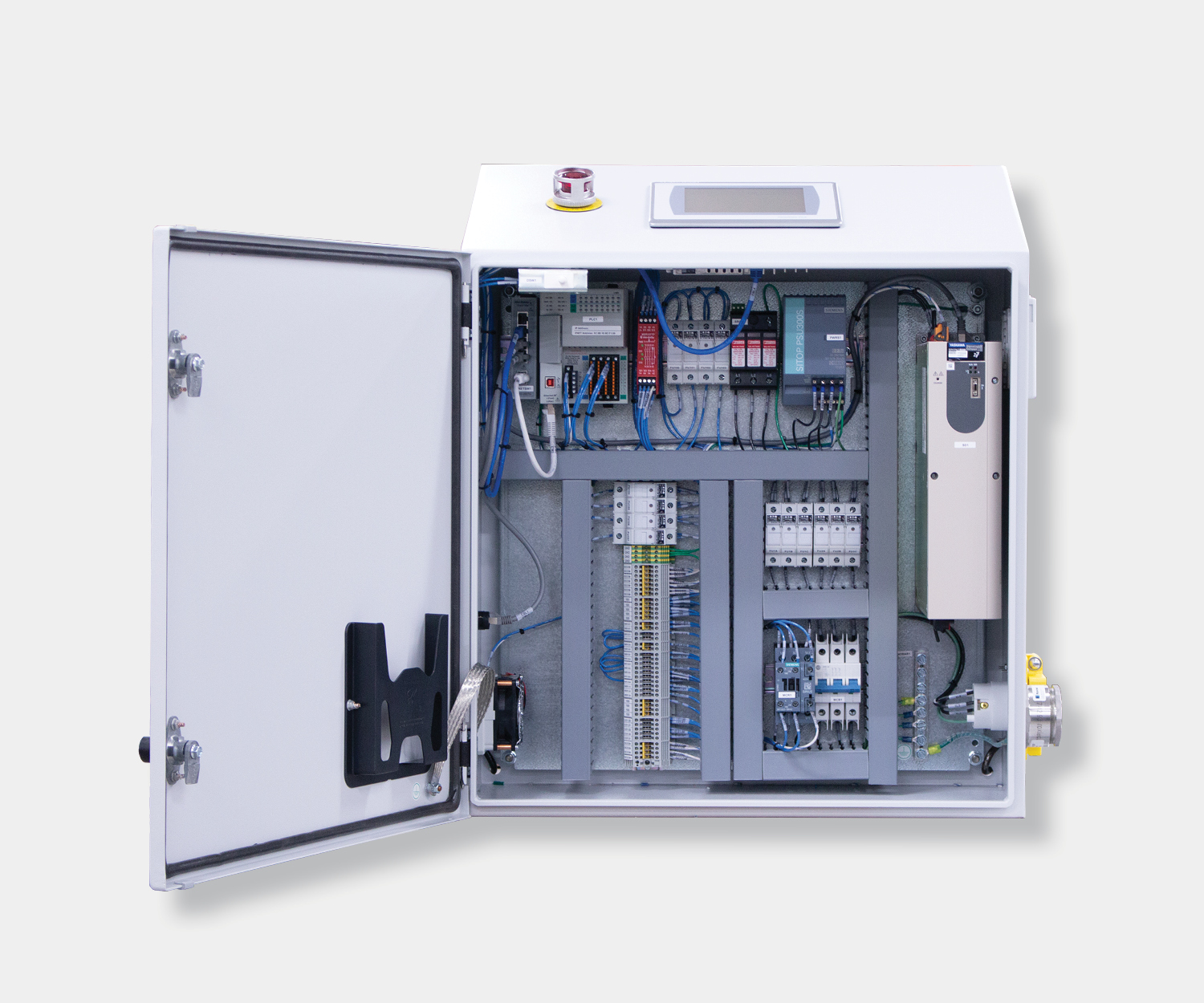
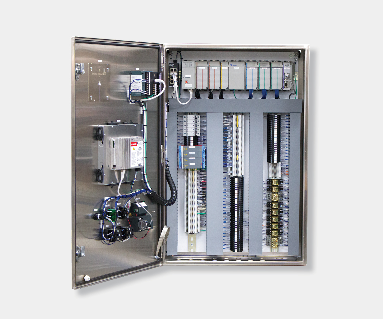
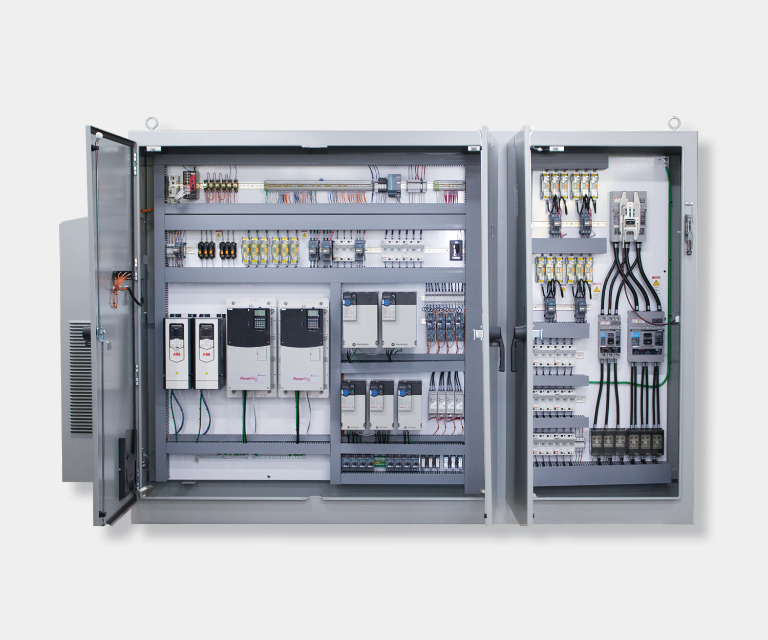
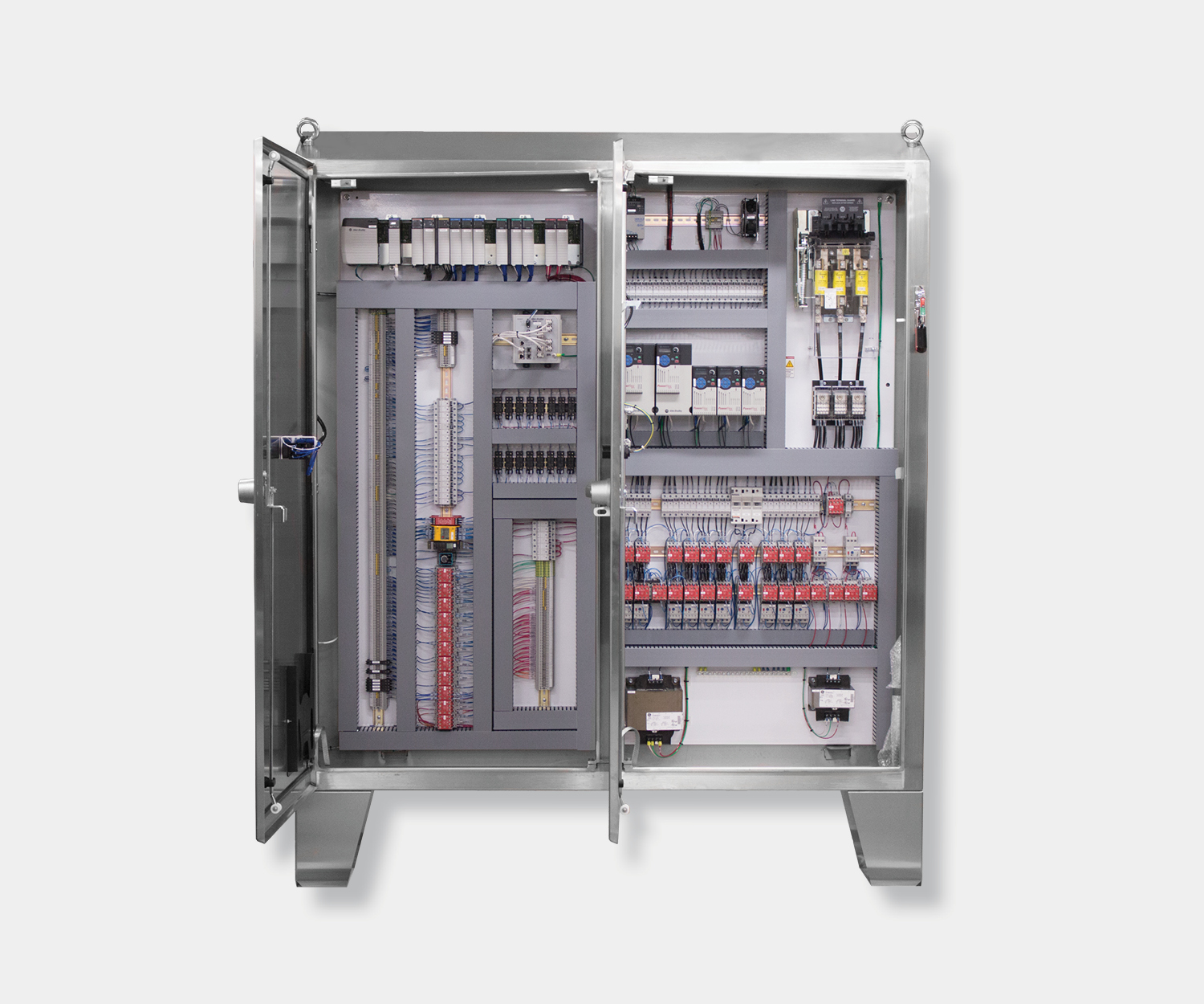
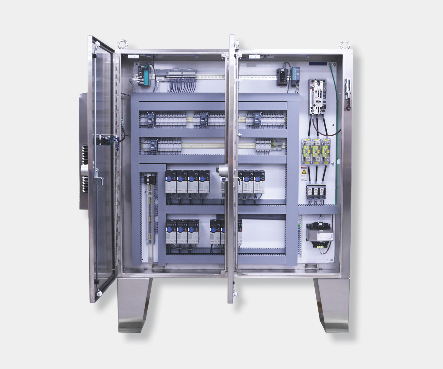
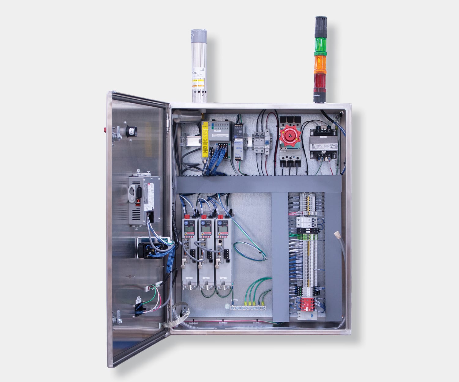
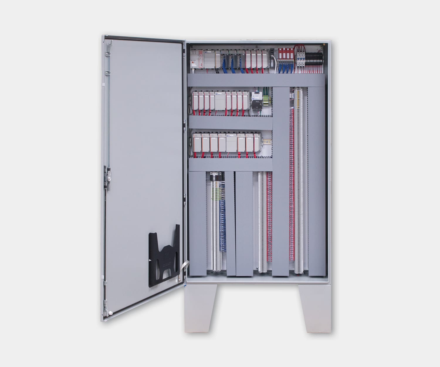
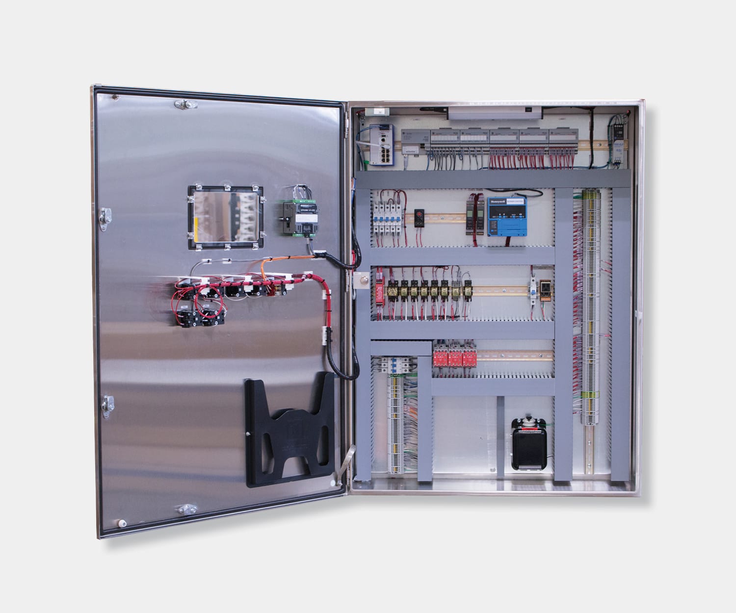
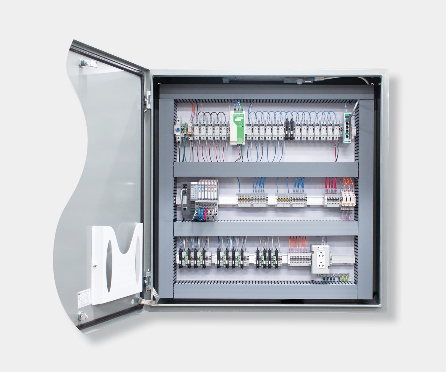
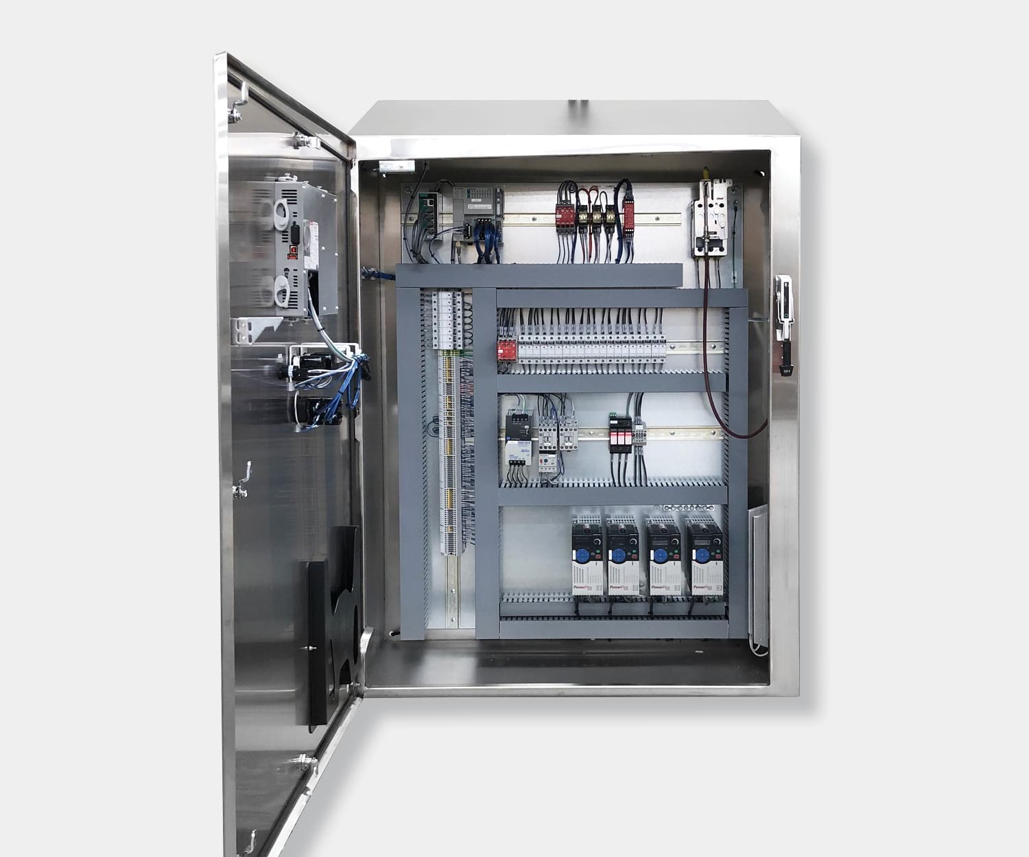
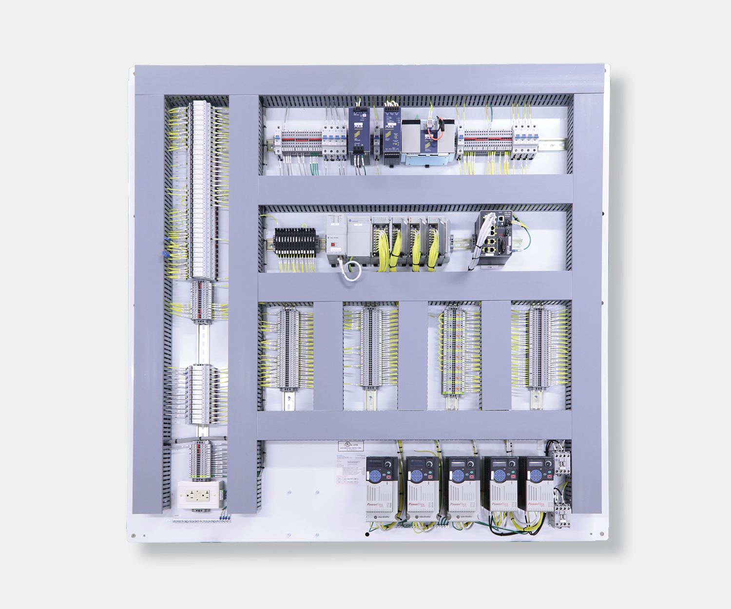
The main components of a PLC consist of a central processing unit (CPU), power supply, programming device, and input and output (I/O) modules.
CPU
The CPU is the brain of the PLC and carries out programmed operations. These operations or outputs are executed based on signals and data provided from connected inputs.
I/O Modules
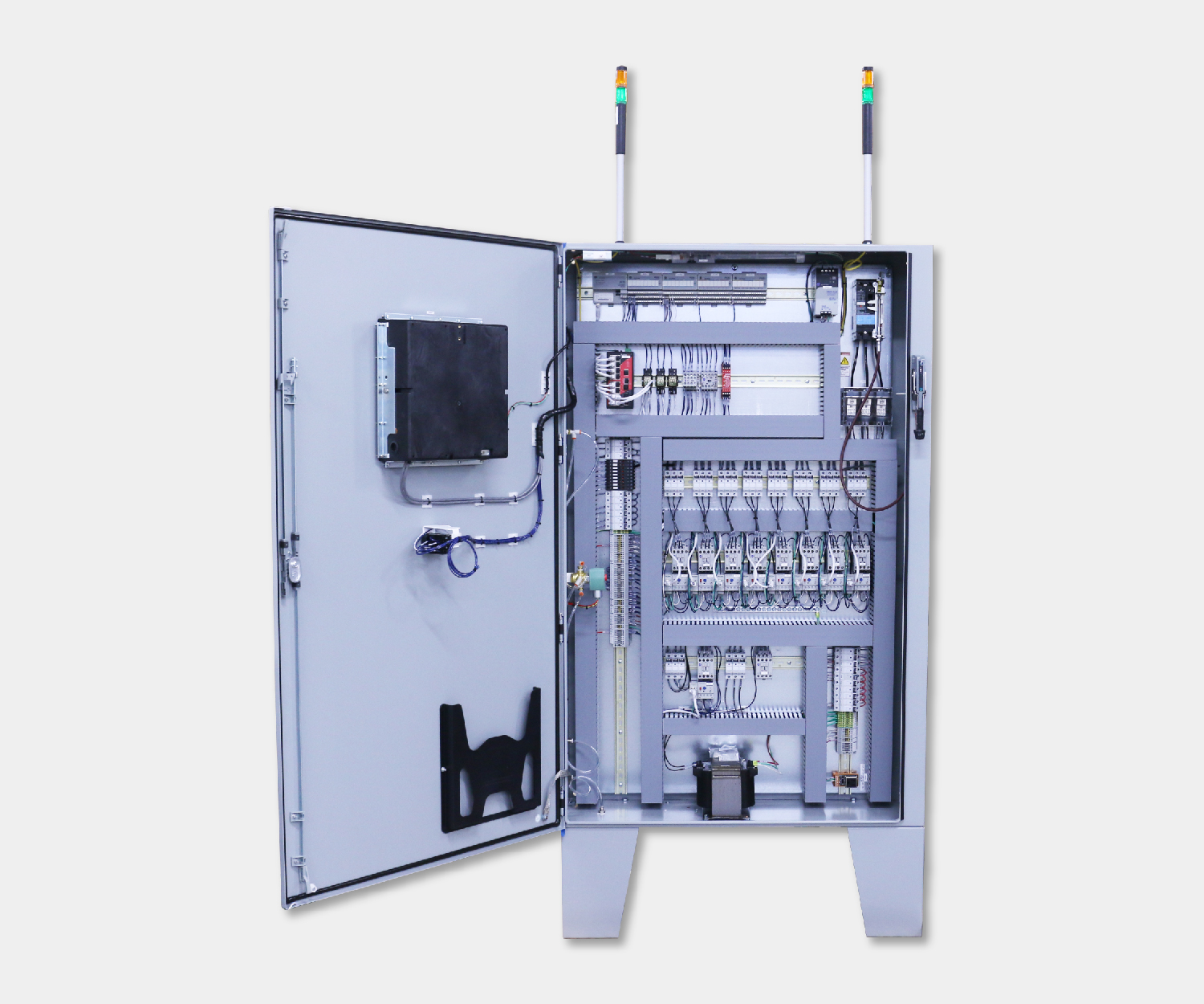
PLC input modules connect various external devices, such as sensors, switches, and push buttons to the PLC to read various digital and analog parameters, such as temperature, pressure, flow, speed, etc. Output modules convert signals from the CPU into digital or analog values to control output devices.
Power Supply
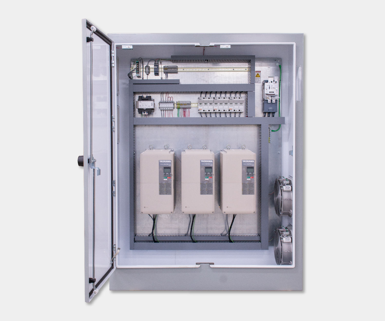
The power supply provides power to the PLC by converting the available incoming AC power to the DC power required by the CPU and I/O modules to operate properly.
Software
The PLC manufacturer typically determines PLC development software. Allen Bradley, Siemens, and GE each have their own software development platforms for programming their PLC models. Once the platform is determined, the actual programming of the PLC logic can be done in a few different methods. The most common methods of PLC programming include Ladder Logic, Function Block, and structured text.
Ladder Logic
Ladder Logic is a graphical PLC programming language and is the most common method of programming. Ladder Logic can be used to execute tasks such as sequencing, counting, timing, data manipulation, and more. Ladder Logic is structured similarly to relay logic; however, the physical switches and coils used in relay logic are replaced by the PLC’s memory locations and I/O.
Structured Text
Structured text is a text-based PLC programming language and is similar to Python, Visual Basic, or C coding languages. Programming with structured text has multiple advantages, such as the program requiring less space due to being text based instead of graphic based. Additionally, the structured text can be combined with other programming languages, such as creating function blocks containing functions written in structured text.
Function Block
Function block PLC programs are represented in the form of graphical blocks. Signals or data flow into the function block from inputs connected to the PLC. When the incoming signals or data triggers the function block’s pre-programmed function, the PLC executes one or more outputs. Function blocks can have standard functions such as timers, counters, calculating min and max values, obtaining averages, and more.
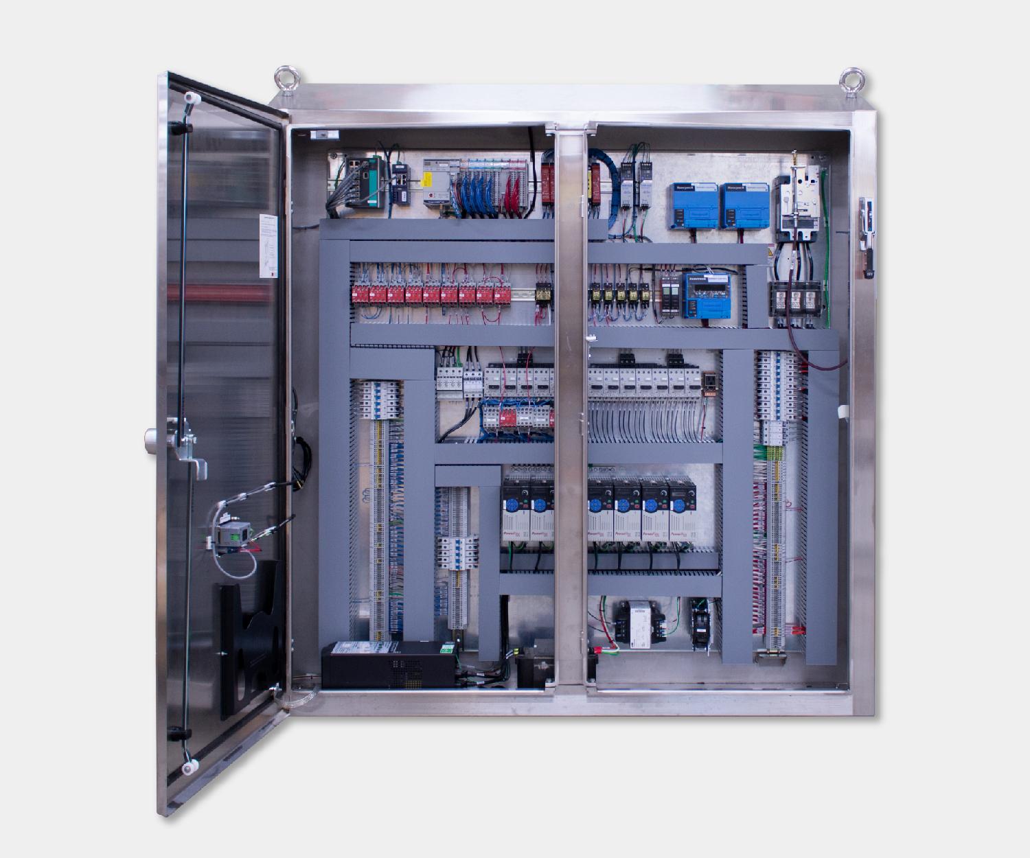
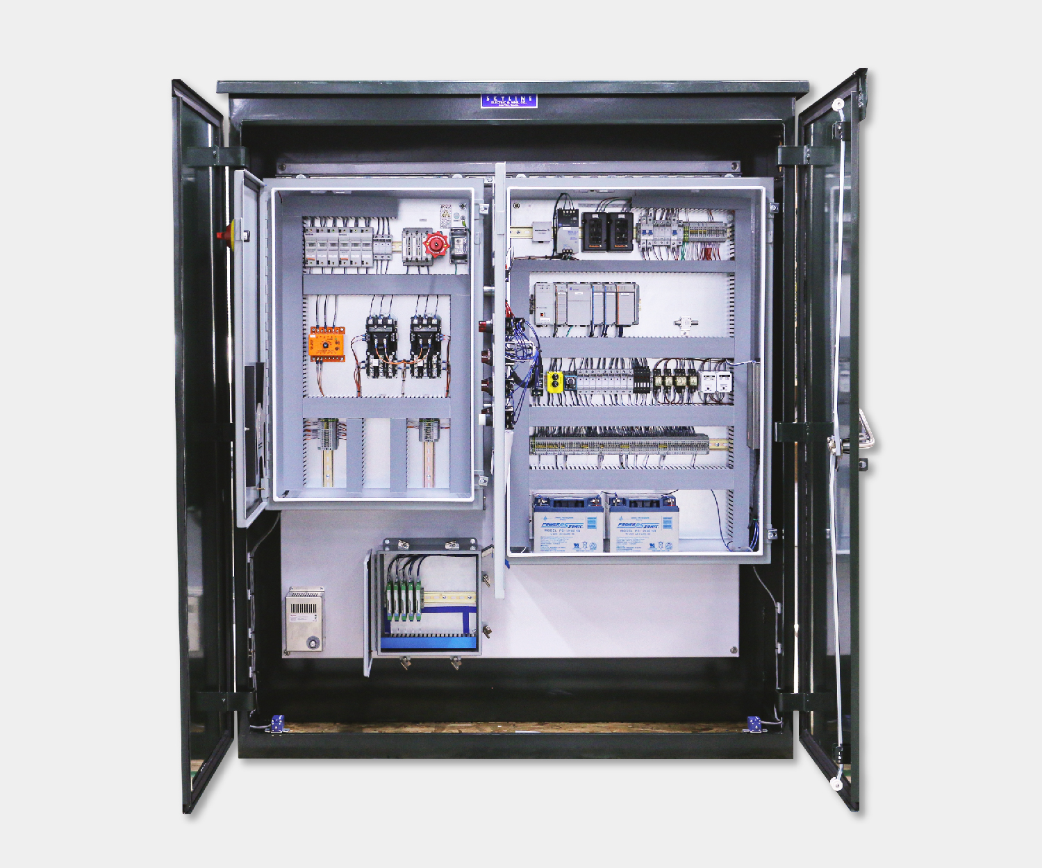
About Process Solutions
Located near Seattle, Washington, Process Solutions has over 30 years of experience providing high quality and reliable control systems. With over 100 engineers and technicians on staff and an output of over 3,000 control panels per year, Process Solutions is the Northwest largest control systems integrator. Process Solutions’ control systems services include custom control panel design, build, and commissioning, HMI programming, PLC integration, energy management and refrigeration systems, SCADA software, and machine monitoring software.