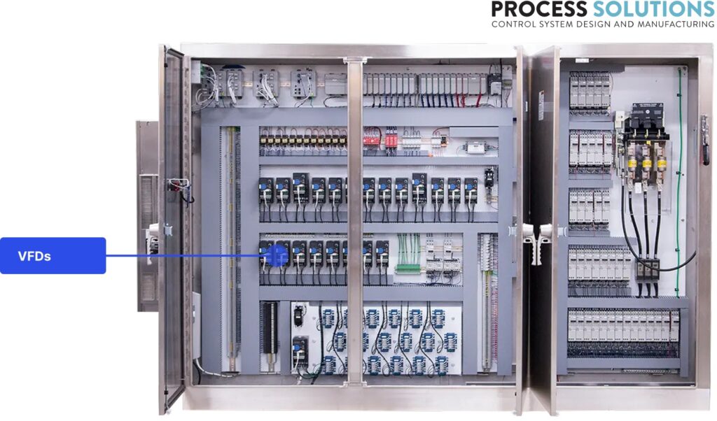
If your control panel runs motors — and most do — you’ll find VFDs inside. They’re on pumps, fans, conveyors, compressors, and just about anything else with a motor that doesn’t need to run flat-out every second it’s on.
How VFDs control motor speed
Motor speed depends on the frequency of the power feeding it. Utility power in North America runs at 60 Hz, which locks a 4-pole motor at about 1,800 RPM. If you want a different speed, you need to change the frequency.
That’s what a VFD does. Inside the drive, three stages work in sequence.
The rectifier converts incoming AC power to DC. This stage takes your facility’s 480V (or 208V, or 600V) AC supply and turns it into a DC voltage on an internal bus.
Capacitors on the DC bus smooth and store that DC energy, bridging the input and output stages.
The inverter uses power transistors (IGBTs) to switch the DC bus voltage on and off in precise patterns, reconstructing AC output at whatever frequency and voltage the application needs. The switching happens thousands of times per second, producing a waveform the motor sees as variable-frequency AC power.
Set the output to 30 Hz and the motor runs at roughly half speed. Set it to 45 Hz and you get three-quarter speed. The VFD adjusts continuously based on commands from the PLC, a local keypad, or an analog signal.
Compare that to throttling a valve on a pump discharge or closing a damper on a fan outlet. Those methods waste energy by fighting the motor’s full output. A VFD eliminates the waste by producing only the output you actually need.
Energy savings and soft starting
The energy case for VFDs is strongest on centrifugal loads (pumps, fans, and blowers), where the affinity laws mean power consumption drops with the cube of speed reduction. Cut speed by 20% and power consumption drops by roughly 50%. Cut speed in half and you’re using about one-eighth the energy.
In practice, facilities typically see 20–60% energy reductions on pumps and fans after installing VFDs. The exact number depends on how much time the motor spends at reduced speed versus full speed. A cooling tower fan that runs at 70% speed most of the year saves dramatically more than a conveyor that’s always at 100%.
The savings compound over time. A 50 HP motor running 8,000 hours a year at an average of 75% speed can save $5,000–$10,000 annually in electricity, depending on your utility rate. The drive often pays for itself in under two years.
VFDs also soft-start motors. Instead of slamming the motor with full voltage and full current on startup, the VFD ramps up gradually. Across-the-line starting can draw 6–8 times the motor’s full load current, but a VFD limits starting current to around 100–150% of full load. That means less voltage dip on your facility’s electrical system and fewer complaints from neighboring equipment.
The gradual ramp also reduces shock loads on couplings, gearboxes, belts, and bearings. This matters most on conveyors and high-inertia loads where hard starts cause real mechanical damage over time. Lower startup stress extends bearing life and reduces winding fatigue, so VFD-controlled motors consistently outlast motors started across the line.
Selecting the right VFD for your application
VFD selection involves matching the drive to your motor, your load, and your environment. Get it right and the drive runs reliably for years. Get it wrong and you’ll be chasing nuisance faults.
Motor HP/kW rating
Start with the motor nameplate. The VFD must be rated for at least the motor’s full load amps (FLA) at the operating voltage. Don’t just match horsepower. A motor with higher-than-typical FLA for its HP rating needs a larger drive.
Oversizing the VFD by one frame size is common practice. It gives you margin for motor tolerance variations, transient overloads, and future motor replacements that might draw slightly more current. The cost difference between adjacent frame sizes is small compared to the headache of a drive that trips under normal operating conditions.
Undersizing is where problems start. An undersized VFD runs at or near its current limit continuously, which shortens capacitor life, triggers overcurrent faults during load spikes, and generates more heat than the panel cooling system was designed to handle.
Voltage class
VFDs are built for specific voltage classes: 208V, 480V, and 600V are the most common in North American industrial applications. The drive’s input voltage must match your facility’s electrical service.
480V drives are the most widely used in industrial settings. They’re available in the widest range of HP ratings and typically offer the best cost-per-horsepower. 208V drives are common in smaller facilities or commercial applications. 600V drives are standard in Canada and some heavy industrial environments.
Mismatching voltage class isn’t an option. A 480V drive on a 208V supply won’t produce rated output, and connecting the wrong voltage can damage the drive immediately.
Constant vs. variable torque
This is where application type drives the selection.
Variable torque loads (pumps, fans, blowers) need less torque at lower speeds. The load follows a square-law relationship with speed, so the drive doesn’t have to work as hard at reduced speeds. VFDs rated for variable torque are typically sized for 110% overload for one minute.
Constant torque loads (conveyors, mixers, positive displacement pumps, extruders) need the same torque regardless of speed. Moving a conveyor belt at half speed still requires the same force to move the product. VFDs rated for constant torque handle 150% overload for one minute.
Sizing a variable torque drive for a constant torque application will cause overcurrent trips during load spikes. If your application is constant torque, make sure the drive is rated for it, which usually means going up one frame size compared to the variable torque rating at the same HP.
Ambient temperature derating
VFD ratings assume a specific ambient temperature, typically 40°C (104°F). If your panel runs hotter than that — and many do, especially in summer or in panels packed with heat-generating equipment — the drive can’t deliver its full rated output.
Manufacturers publish derating curves that show how much output current you lose per degree above the rated ambient. A rough rule of thumb: expect to derate by 1–2% per degree C above 40°C. At 50°C ambient, you might lose 10–15% of rated capacity.
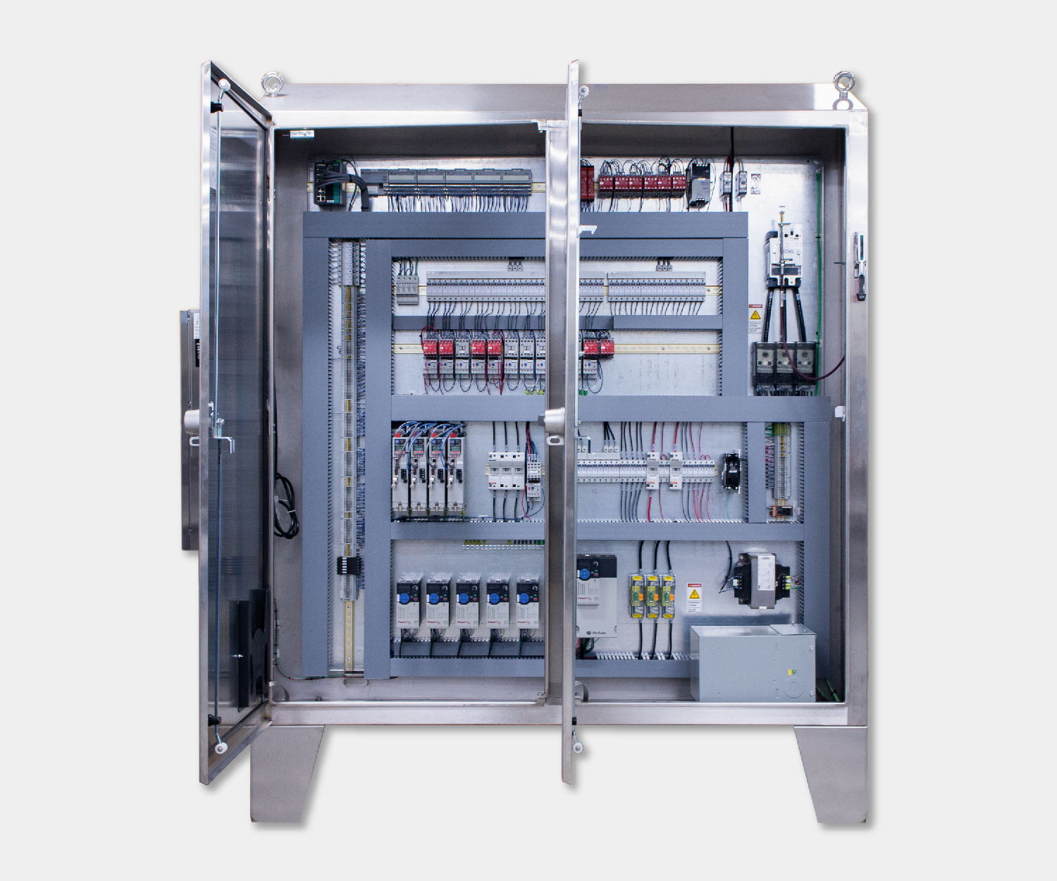
You have two options: oversize the drive to account for the derating, or improve panel cooling so the drive operates within its rated temperature. In practice, panels with multiple VFDs almost always need active cooling: filter fans at minimum, and often air conditioning for larger installations.
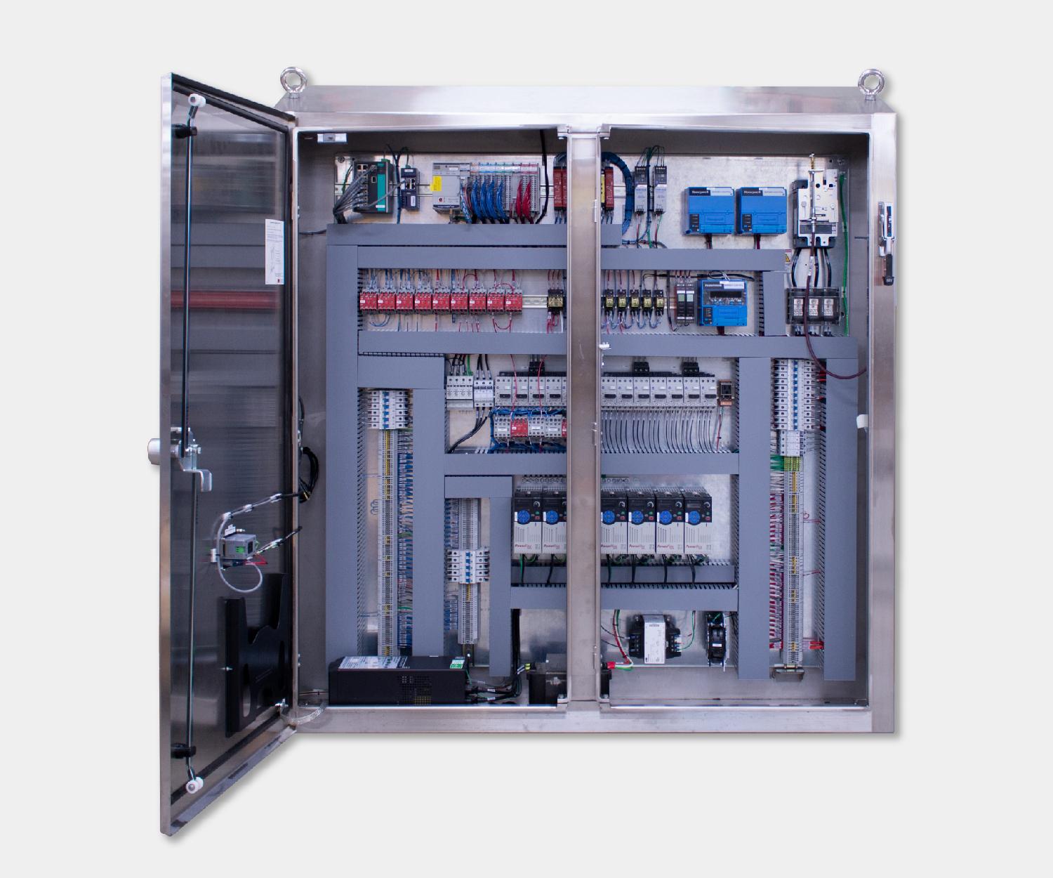
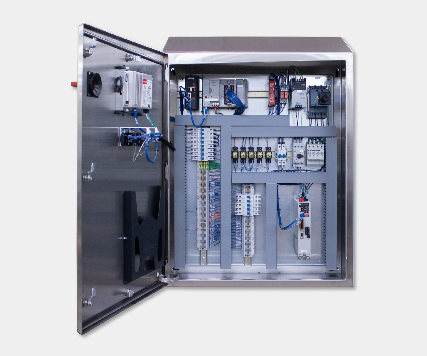
Installation and panel layout considerations
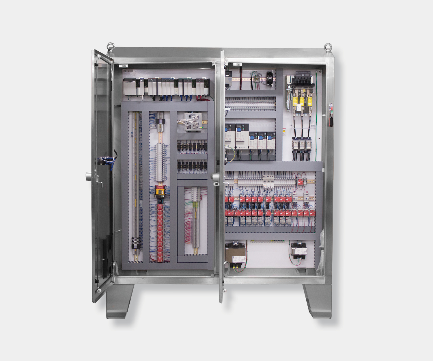
Where you put the VFD in the panel and how you route cables around it matters more than most people expect. VFDs are the biggest heat generators and the biggest noise sources in a typical control panel.
Heat dissipation
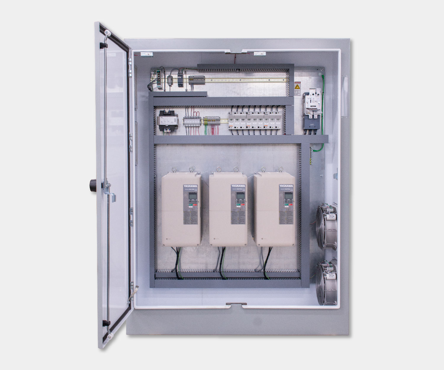
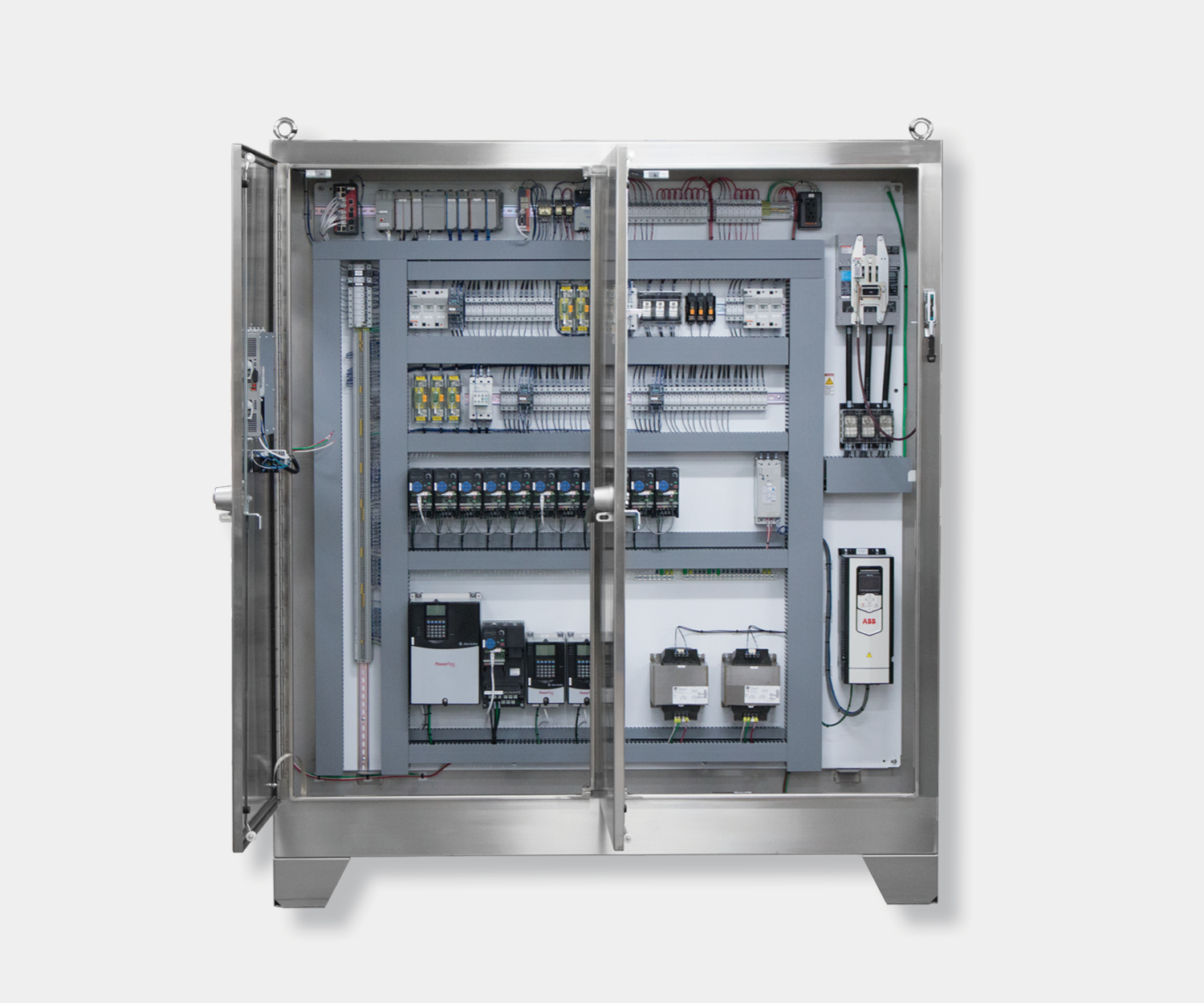
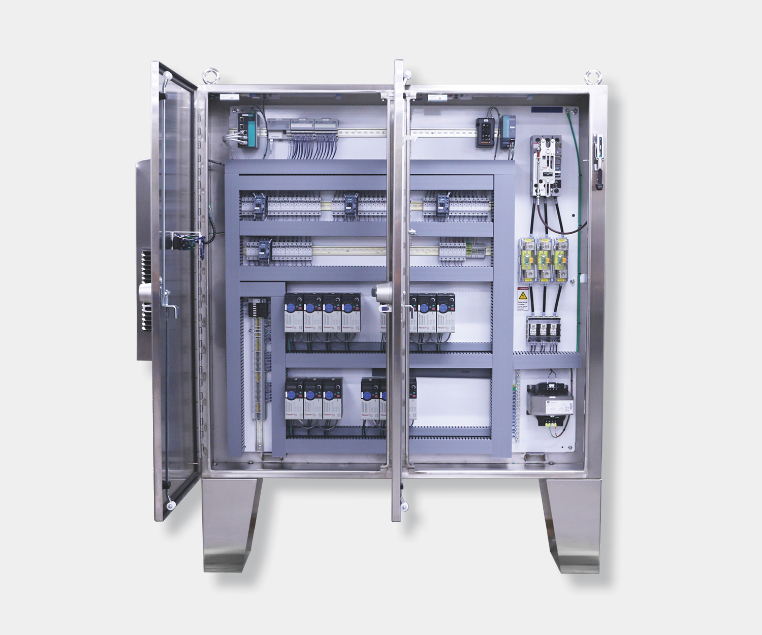
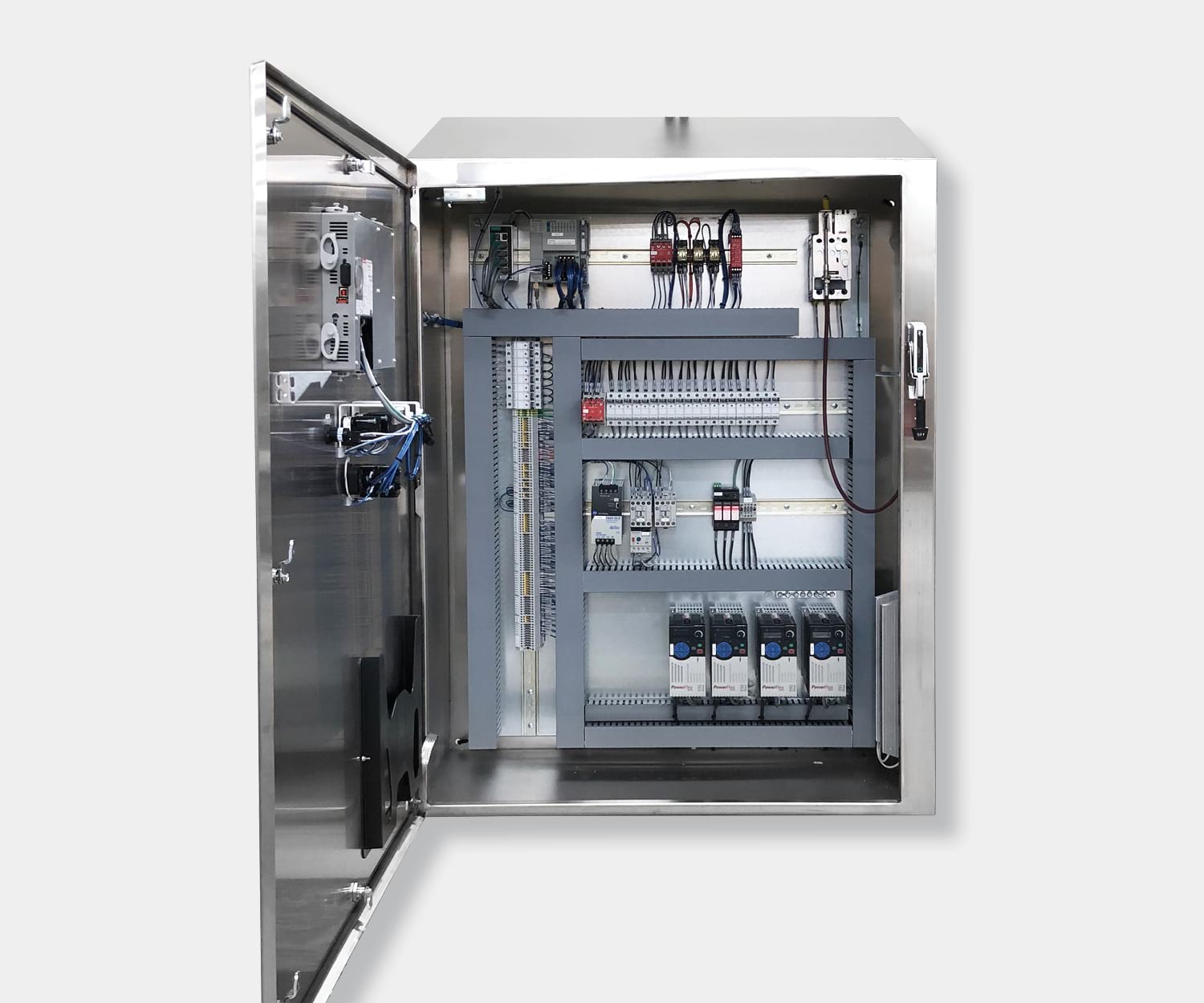
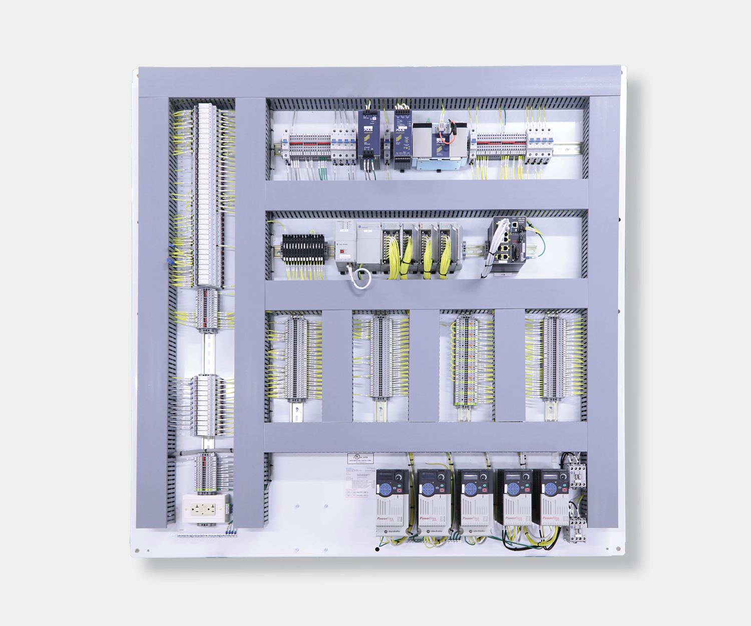
A VFD converts about 2–4% of the power it handles into heat. A 50 HP drive on a 480V system dissipates roughly 1,000–1,500 watts into the enclosure. Put three of those in a panel and you’ve got a serious cooling problem. Mount drives near the top of the panel where heat naturally rises toward exhaust fans, and maintain the manufacturer’s required clearance above and below for airflow.
Spacing and airflow
Most VFD manufacturers require 4–6 inches of clear space above and below the drive for ventilation. Side-to-side spacing varies. Some drives allow zero-stacking, others need clearance. Check the installation manual for your specific drive. Ignoring these requirements leads to overtemperature faults and shortened drive life.
Input and output filtering
VFDs generate electromagnetic interference from the high-frequency switching in the inverter stage. Line reactors or EMI filters on the input side reduce harmonics fed back to the power system. Output filters or reactors protect motor windings from voltage spikes, especially on long cable runs. The power conditioning filter article in this series covers filtering in more detail.
Cable routing
Keep VFD output cables (drive to motor) separated from signal and communication cables. The high-frequency switching noise in output cables can couple into nearby signal wiring and cause erratic sensor readings or communication errors. A good rule: maintain at least 12 inches of separation, or use shielded cable and grounded conduit for the output run. Cross power and signal cables at 90-degree angles when they have to meet.
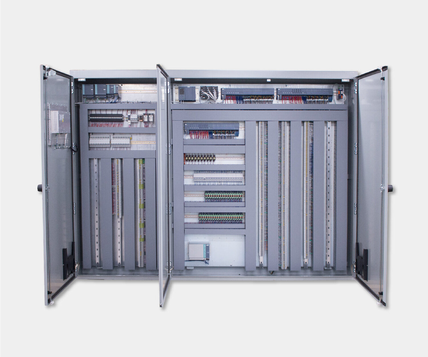
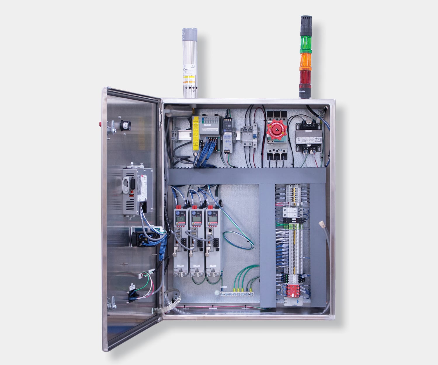
Communication and network integration
Modern VFDs don’t just respond to a hardwired analog signal anymore. Most industrial drives connect directly to the PLC over the plant’s industrial Ethernet network.
The protocol depends on your PLC platform. Allen-Bradley systems use EtherNet/IP. Siemens uses PROFINET. Schneider and many others support Modbus TCP. Most VFD manufacturers offer communication adapters for all major protocols, so the drive can work with whatever PLC you’ve got.
Over the network, the PLC can send speed commands, start and stop the drive, read operating data like current and frequency, monitor fault codes, and even change drive parameters without walking to the panel. That’s a big upgrade from the old approach of running a 4–20mA analog signal for speed reference plus discrete wires for start, stop, forward, reverse, and fault.
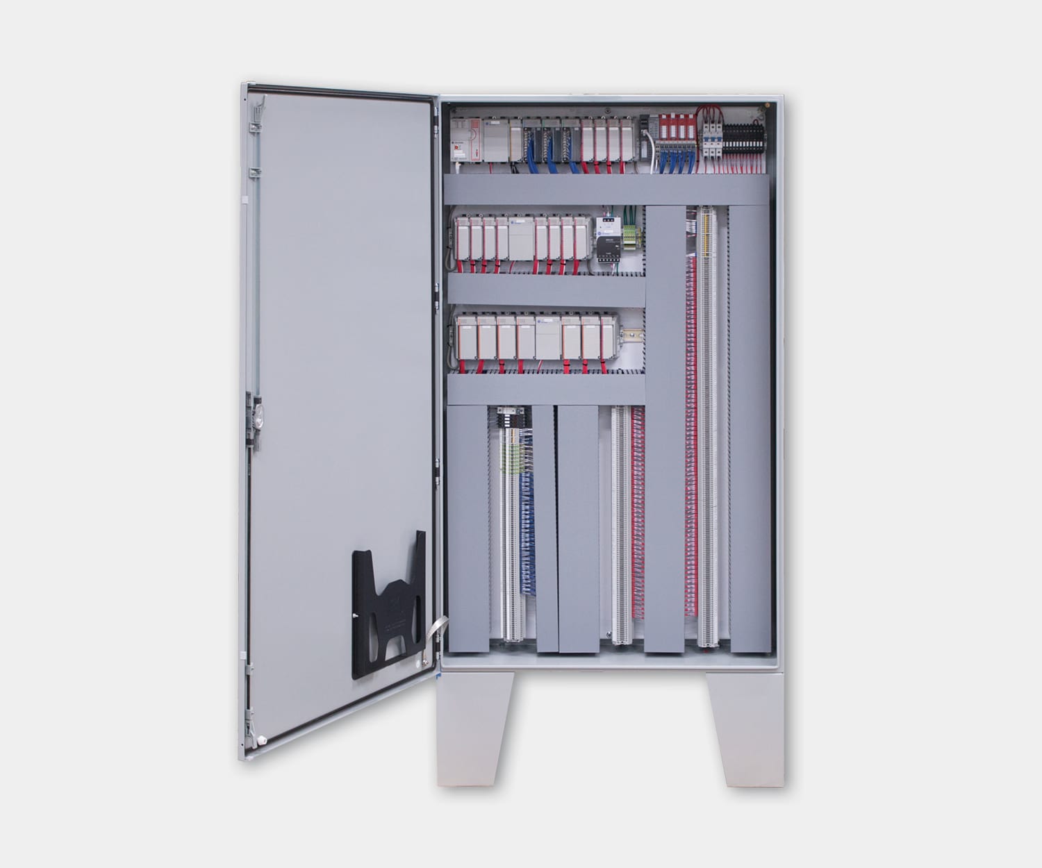
Network control simplifies wiring. Instead of a bundle of analog and discrete wires between the PLC and each drive, you run a single Ethernet cable. For a panel with six VFDs, that’s a meaningful reduction in wiring labor, terminal strip space, and potential failure points.
The tradeoff is that network communication adds a dependency. If the network switch goes down, the PLC can’t command the drives. For critical applications, some engineers keep a hardwired stop circuit as a backup so the motor can be stopped independently of the network. The industrial network switches article in this series covers network reliability and redundancy in more detail.
Getting VFDs right in your panel
VFDs are among the most impactful components in a control panel. They save energy, extend motor life, and give you precise speed control that isn’t possible with fixed-speed motor controllers. But they also generate heat and electrical noise, and they need to be sized and installed correctly to deliver on those benefits.
The key decisions (drive sizing, torque rating, panel layout, cooling) are all connected. An undersized drive in a hot panel with poor airflow will cause more problems than it solves. Getting these details right during the design phase is what separates a panel that runs reliably from one that trips drives all summer.
Want to see how VFDs fit into the bigger picture? Our Control Panel Anatomy guide walks through every major component and how they work together.
Need help specifying VFDs or designing panels that handle heat and wiring properly? We can help you get the details right before anything gets built.
Frequently asked questions
Q: Can any motor be controlled by a VFD?
Most standard induction motors can run on a VFD, but inverter-duty rated motors handle the voltage spikes and heat better. The high-frequency switching in a VFD’s inverter creates voltage peaks that stress motor winding insulation. Inverter-duty motors (rated per NEMA MG1 Part 31) are built with enhanced insulation to handle this. Running a non-inverter-duty motor on a VFD long-term can degrade winding insulation and shorten motor life.
Q: How much energy can a VFD actually save?
On centrifugal loads like pumps and fans, reducing speed by 20% cuts energy use by roughly 50% thanks to the cube law. Facilities typically see 20–60% reductions. Constant-speed applications won’t see energy savings, but they benefit from soft starting and precise speed control.
Q: What’s the difference between a VFD and a soft starter?
A soft starter only ramps voltage during startup, then bypasses itself at full speed. A VFD controls speed continuously. If the motor always runs at full speed, a soft starter costs less. If you need variable speed or energy savings at reduced speed, use a VFD.
Q: Do VFDs damage motors?
Not when properly specified. The concern comes from voltage spikes created by the VFD’s high-frequency switching, which can stress motor winding insulation over time. Inverter-duty motors are built to handle this. For standard motors, adding an output reactor or dV/dt filter between the drive and motor protects the windings. Most motor failures attributed to VFDs trace back to undersized drives, missing filters, or cable runs that exceed manufacturer limits.
Q: Do VFDs require special wiring?
Yes. VFD output cables should be shielded and kept separated from signal wiring. Long cable runs cause voltage reflections that damage motor winding insulation. Most manufacturers limit cable distance to 100–300 feet depending on whether output reactors are used.