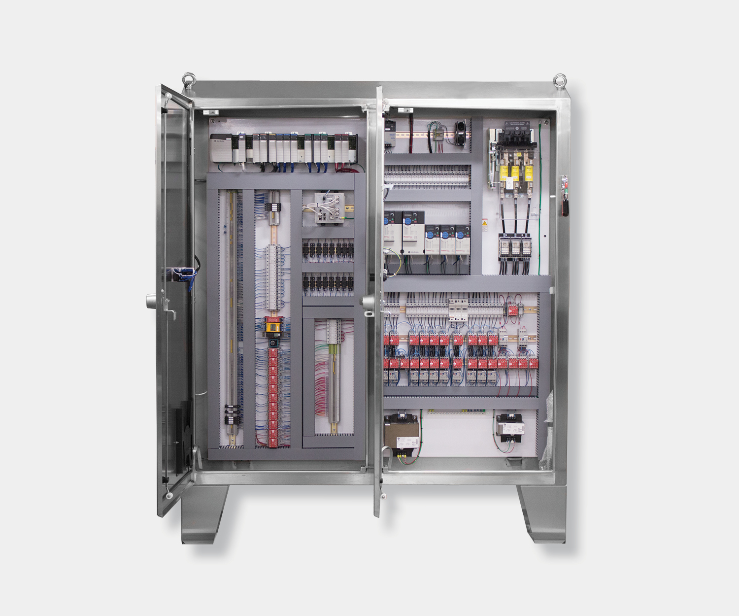
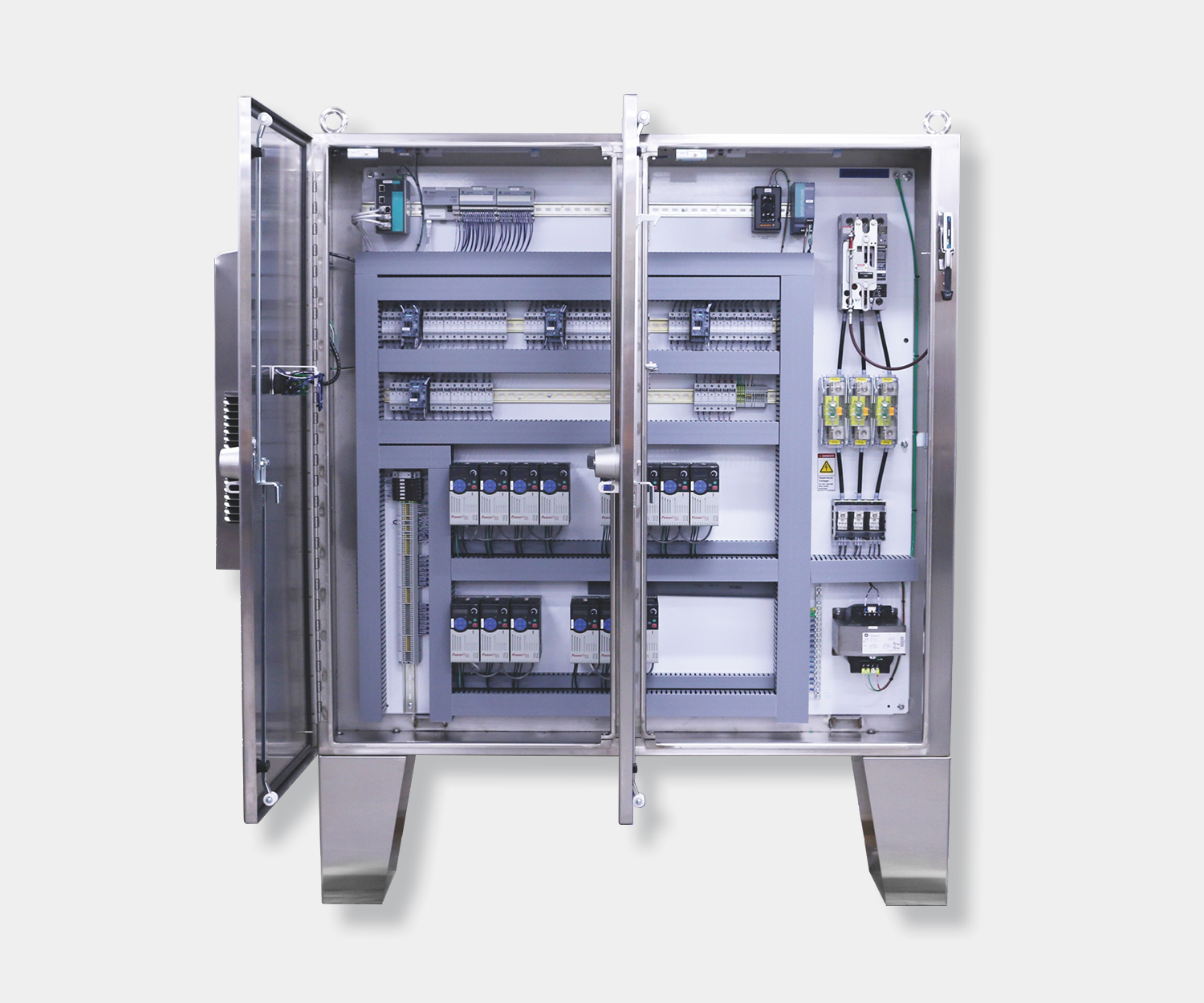
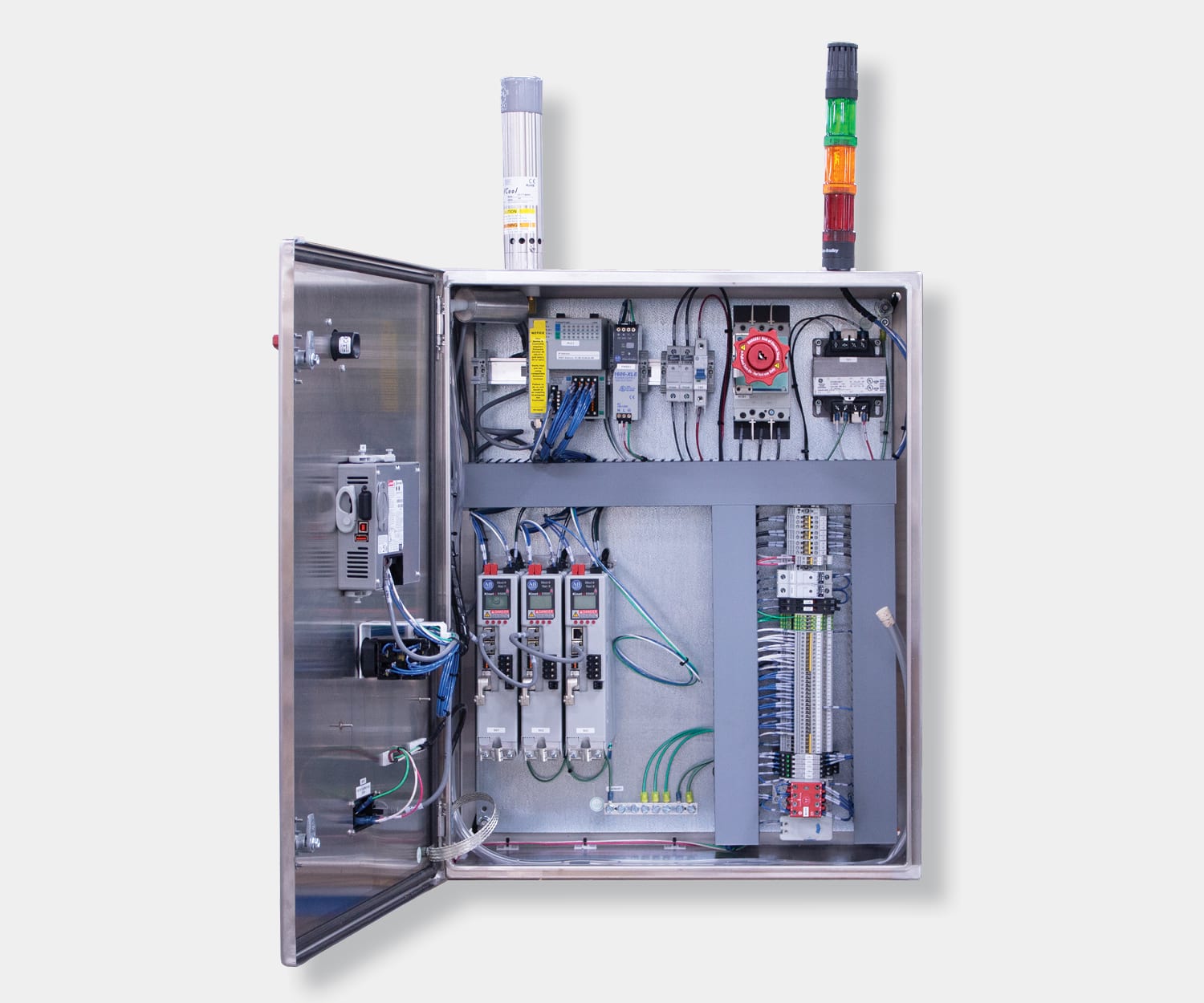
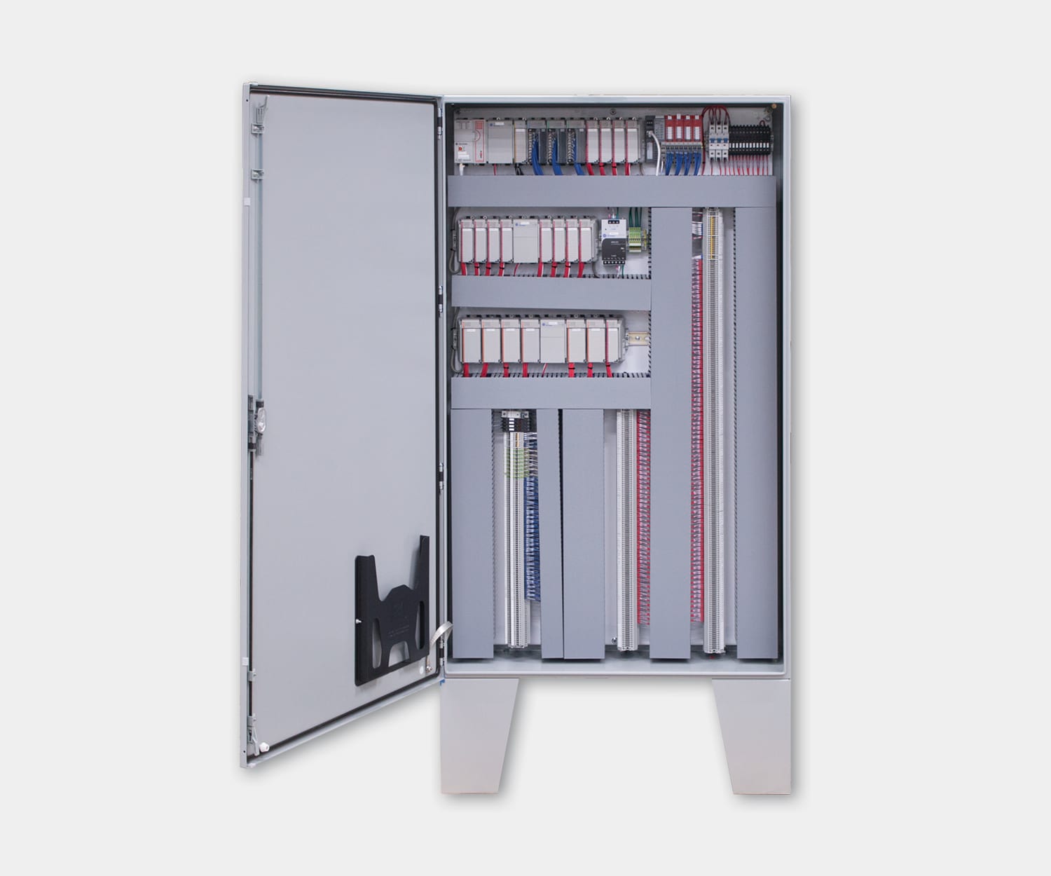
Some of the hardest control panel problems to diagnose turn out to be power quality problems. Intermittent faults, garbled network traffic, analog signals that drift for no reason. You swap the PLC, the problem stays. You replace the sensor, same thing. When nothing in the logic or the hardware explains what you’re seeing, electrical noise is worth investigating.
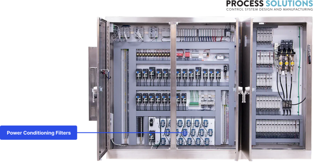
VFDs, motor contactors, and even the facility’s own electrical system can generate electromagnetic interference that bleeds into sensitive control circuits. Power conditioning filters keep that noise from reaching your electronics.
They’re one of the least glamorous components in the panel. They’re also one of the most commonly skipped — which means when noise is the problem, it often goes unresolved longer than it should.
Where electrical noise comes from in a control panel
VFDs are the biggest noise generators inside a typical panel. They work by chopping DC voltage into a simulated AC waveform using high-frequency switching, usually between 2 kHz and 16 kHz. That switching creates conducted EMI that travels back through the power lines and radiated EMI that couples into nearby wiring.
Motor contactors are the second major source. Every time a contactor opens or closes under load, the breaking arc generates a burst of high-frequency noise. In a panel with a dozen motor starters cycling throughout the day, that adds up.
External noise enters through the main power feed. Other equipment on the same electrical service, welders, large motors starting across the line, even utility switching events, all push noise into your panel from outside.
Two types of noise matter here. Conducted EMI travels along the power conductors themselves. Radiated EMI propagates through the air and couples into signal cables and control wiring. Power line filters target conducted noise directly. Radiated noise requires shielding, cable separation, and proper grounding, which are layout and wiring issues rather than filter issues.
How EMI/RFI filters work
A power line filter is a passive circuit built from inductors and capacitors arranged to block high-frequency noise while allowing 50/60 Hz power to pass through cleanly.
Filters handle two types of noise differently. Common-mode noise appears equally on both power conductors relative to ground. It’s the type VFDs generate most. Differential-mode noise appears between the two power conductors. Contactor arcing and utility disturbances tend to produce this kind.
A basic single-stage filter has a common-mode choke (an inductor wound so that normal power current cancels out magnetically, but noise current doesn’t) plus capacitors from each line to ground. This handles common-mode noise well. Adding differential-mode capacitors across the lines handles noise between conductors.
Two-stage filters stack two filter sections in series for steeper attenuation across a wider frequency range. You’ll see these on panels with multiple VFDs or where the sensitive equipment is particularly noise-intolerant.
The spec that tells you how well a filter performs is insertion loss, measured in decibels (dB) across a range of frequencies. A filter’s datasheet will show an attenuation curve plotting dB of noise reduction against frequency. More dB at your problem frequency means better suppression. A filter that looks great at 1 MHz might do nothing at 10 kHz where your VFD switching noise actually lives, so match the filter’s performance curve to your actual noise source.
Filter placement and installation
Where you mount the filter matters as much as which filter you pick. Install it wrong and you can actually make noise problems worse.
The basic rule: mount the filter as close as possible to the noise source or the panel entry point. For VFD input filtering, the filter goes right at the VFD’s power input terminals. For main panel filtering, it goes at the point where power enters the enclosure, right after the fused knife disconnect.
The single most common installation mistake is running input and output wiring together. The filter works by blocking noise on the input side from reaching the output side. If the input and output wires run next to each other, the noise couples right around the filter through the air. Keep input and output wiring physically separated. Different wire duct runs. Different conduit if possible.
Grounding is the other installation detail that trips people up. The filter’s ground connection must be short, solid, and bonded directly to the panel backplate or enclosure. A long ground wire adds inductance that reduces the filter’s effectiveness at high frequencies. Bolt the filter to the backplate with good metal-to-metal contact. Don’t rely on painted surfaces for grounding.
One more thing worth mentioning: filters generate leakage current to ground through their capacitors. This is normal and expected, but it means your ground fault protection needs to account for it. If you install multiple filters in a panel and start tripping ground fault devices, the cumulative leakage current is probably why.
Selecting the right filter for your application
Start with three basic specs:
Voltage and current rating. The filter must be rated for your system voltage (typically 480V for industrial panels) and carry the full load current of whatever it’s feeding. Undersizing the current rating causes the filter to overheat and fail.
Attenuation requirements. Look at the noise source frequency and how much suppression you need. VFD switching noise lives in the low kilohertz range. If your filter’s attenuation curve shows good performance at those frequencies, you’re in the right ballpark.
Leakage current. Every filter with line-to-ground capacitors has some leakage. Standard filters might leak 3-5 mA. In panels with multiple filters, that adds up. If you’re on a system with sensitive ground fault protection or in a medical/life-safety application, look for low-leakage filter options.
Beyond those three, you’ll need to decide between single-stage and two-stage designs. Single-stage filters handle most VFD noise problems and cost less. Two-stage filters are for situations where the noise environment is harsh, you’re filtering for especially sensitive equipment, or a single stage doesn’t provide enough attenuation in the frequency range that matters.
For panels with multiple VFDs, filter each drive individually rather than trying to put one large filter on the main feed. Individual filters let you match the filter to each drive’s specific current and noise characteristics, and they isolate drives from each other’s noise.
One related component worth mentioning: load reactors, sometimes called output reactors. These go on the output side of the VFD, between the drive and the motor. They solve a different problem than the input-side EMI filters discussed above. When motor cable runs exceed about 100 feet, the VFD’s fast switching pulses create voltage reflections in the cable that can double the peak voltage at the motor terminals. That damages motor winding insulation over time. A load reactor installed at the VFD output dampens those voltage spikes before they travel down the cable. They won’t clean up EMI on your power bus, but on long cable runs they’re essential for protecting the motor.
Symptoms of poor power quality
Here’s why power conditioning filters matter: the symptoms of EMI problems look like everything except EMI problems.
Intermittent PLC faults with no clear cause. The PLC throws a fault, you check the code, everything looks fine. It clears on its own and doesn’t come back for hours or days. Then it happens again. If you can’t correlate the faults with any process event, noise on the power rail is worth investigating.
Communication errors on industrial networks. EtherNet/IP, PROFINET, Modbus TCP — all of them can be disrupted by conducted EMI. You’ll see CRC errors, dropped packets, or devices intermittently dropping off the network. The pattern often matches when VFDs are ramping or motor starters are cycling.
Analog signal noise. A 4-20 mA signal that bounces or drifts when nearby motors start. A temperature reading that suddenly jumps 10 degrees for no reason. These point to noise coupling into the signal wiring, often from conducted EMI on shared power circuits.
Unexplained sensor behavior. Proximity sensors that false-trigger. Encoders that miss counts. Photoelectric sensors that see things that aren’t there. When the sensor hardware checks out fine but the readings don’t make sense, look at what’s sharing power with it.
The common thread: these problems tend to be intermittent, correlate with motor or VFD activity, and resist every fix that doesn’t address the underlying power quality.
Filtering the noise before it becomes a problem
Power conditioning filters won’t solve every electrical noise issue in a panel. Radiated EMI, bad cable routing, and grounding problems need their own fixes. But for conducted noise on power lines, which is the most common source of unexplained intermittent faults, a properly selected and installed filter is the straightforward answer.
Want to see how power conditioning filters fit into the bigger picture? Our Control Panel Anatomy guide walks through every major component and how they work together.
Dealing with intermittent panel issues that nobody can explain? It might be a power quality problem. We can help you track it down and fix it.
Frequently asked questions
Q: Do I always need a power line filter if I have VFDs in my panel?
Most VFD manufacturers recommend input line filters, and many installations need them to meet EMC regulations. Even where not strictly required, filters prevent noise from one VFD from disrupting PLCs, sensors, and network switches in the same panel.
Q: Can a power filter fix my PLC communication errors?
If the communication errors come from conducted EMI on the power lines, possibly. But comm issues also come from cable routing, grounding problems, and network configuration. A filter is one piece of the puzzle. Start by checking whether the errors correlate with motor or VFD activity.
Q: What’s the difference between a line reactor and an EMI filter?
A line reactor is an inductor installed on the input side of a VFD that reduces harmonic current and smooths current spikes. An EMI filter uses both inductors and capacitors to target a broader range of high-frequency noise. They do different things and are sometimes used together on the same VFD. A load reactor (or output reactor) is a separate device that goes on the VFD’s output side to protect motor windings from voltage spikes on long cable runs, typically 100 feet or more.
Q: How do I know if my filter is installed correctly?
The filter should be mounted close to the noise source or panel entry point. Input and output wiring must be separated, not bundled or run in the same duct. The ground connection should be short and bolted directly to the backplate with clean metal-to-metal contact.
Q: Can electrical noise damage components, or does it just cause malfunctions?
Mostly malfunctions. Conducted EMI causes erratic behavior, false signals, and communication errors. It rarely destroys components outright. But persistent noise can shorten the life of sensitive electronics over time, and the downtime from chasing intermittent faults gets expensive on its own.